Learning Goals
Learning Goals:
- Students will investigate variables that may affect the output of an energy conversion device (wave attenuator).
- Students will interpret data to identify which variables increase electrical output for these model wave attenuators.
- Students will communicate results from scientific inquiry to identify factors that are important to optimizing the design of a wave attenuator.
Materials List
Handouts
- Student Science Journals
Classroom Supplies
- 100-quart Tote
- Water to fill the tote approximately 5 inches deep
- 2L Soda bottle
- 1 Galvanometer or Vernier LabQuest2 with Vernier instrumentation amplifier
- Needle nose pliers or wire cutter
- Scissors
- Hot glue gun
- Sandpaper
- Metronome
- Laptops, Chromebooks, or computers
Group Supplies (3-4 per group)
- 90cm Magnet wire
- 1 Rare earth magnet
- 2 3 1/2 x 7 x 1 1/4 inch Foam
- 1 7/8 x 3/4 inch Acrylic tube
- 1 3/4 x 3 inch Acrylic tube (used for wire)
- 1 1/4 20 4 inch Bolt
- 2 1/4 20 Nuts
- 2 1 1/2 inch L bracket
- 90cm of Duct tape
- Roll of scotch tape
Important Links
Featured Image Description
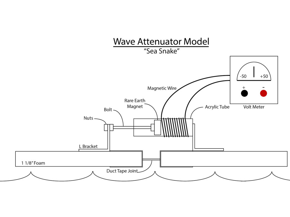
Diagram of a Wave Attenuator Model “Sea Snake”. Sitting over a line representing waves are two rectangles labeled “1 1/8″ Foam” Between these rectangles ins a line labeled “Duct Tape Joint” On each foam rectangle is an L Bracket with the bracket pointed up. On the left side Nuts support a Bolt with a Rare Earth Magnet that is inside an Acrylic Tube that is parallel to the foam. The Acrylic Tube is wrapped in Magnetic Wire. Connected to the Wire and sitting in the upper right of the diagram is a Volt Meter diagram.

